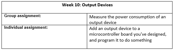
Week 10: Output Devices
This week focuses on measuring the power consumption of an output device as a group assignment and adding an output device to a microcontroller board for the individual assignment.
Group Assignment
Group Assignment: Measure the power consumption of an output device, document your work on the group work page, and reflect on your individual page what you learned.
Output Device Selected
For this assignment, we selected a servo motor model MZ996. This type of servo is commonly used in electronic projects due to its metal gears, which offer better resistance and durability during mechanical movements.
Connection Setup
The servo motor has three wires:
- VCC (red) → 5V DC power supply
- GND (black or brown) → Ground
- Signal (orange or yellow) → PWM output (e.g., Arduino pin)
The servo is controlled using a PWM signal and operates at 5V DC.

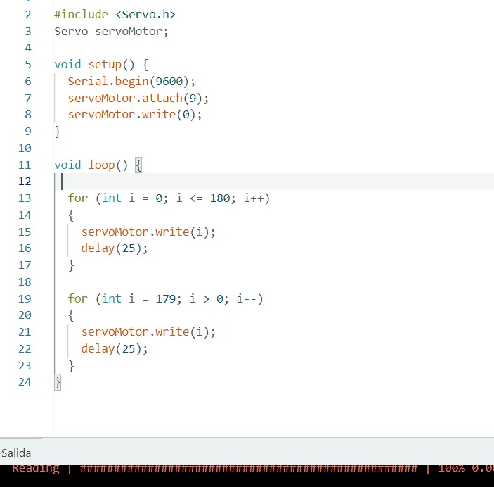
Program Execution
A basic program was uploaded to the development board to rotate the servo motor periodically.
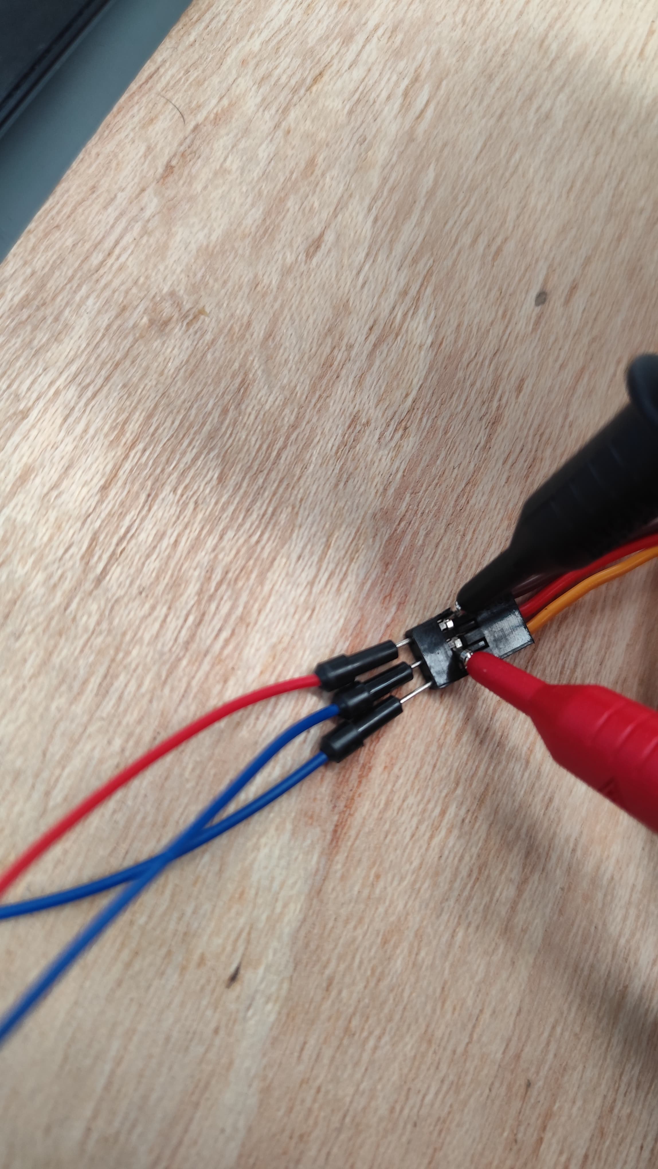
Measurement Procedure
To measure the power consumption:
- Voltage was measured in parallel with the servo motor.
- Current was measured in series.
A digital multimeter was used to capture the voltage and current values during the operation of the servo.
Observations
We recorded the following observations:
- Voltage behavior during operation: Voltage variation video
- Current behavior during operation: Current variation video
Since the servo was not under load (not moving any external weight), the current consumption remained low and stable.
Test Videos
We embedded videos showing the voltage and current behavior:
Group Reflection
The measurement of power consumption showed that the voltage remained around 5V with minor fluctuations, and the current draw was minimal due to the unloaded condition of the motor. Proper use of the multimeter (parallel for voltage, series for current) was essential for accurate measurements.
Individual Reflection
I learned the importance of understanding power consumption in output devices and how it varies depending on load conditions. This exercise also reinforced my skills in using measurement tools effectively.
Individual Assignment
Individual Assignment: Add an output device to a microcontroller board you've designed and program it to do something.
This week, Neil introduced us to output devices and shared several examples we could explore. The task was to connect an output device to a board we designed, program it, and make it work. For this assignment, I decided to create a board with multiple LEDs simulating a traffic light, where each LED turns on individually based on a programmed time sequence. I used the development board I manufactured during the Electronics Production week, which features an ATtiny412 chip with analog and digital inputs and outputs.
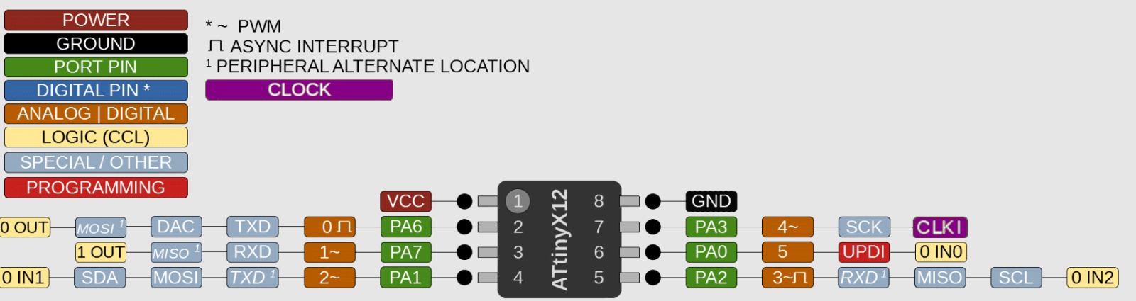
1. Planning the Output Device
The ATtiny412 board I designed has several pins available for digital outputs. For this project, I chose to use three digital pins to control three LEDs (red, yellow, and green) to mimic a traffic light sequence. Below is an image showing the pinout of the board.
2. Programming Setup
To upload the program to the ATtiny412, I used an Arduino Nano as a programmer, communicating through the UPDI port. This setup allowed me to easily transfer the code to the microcontroller.
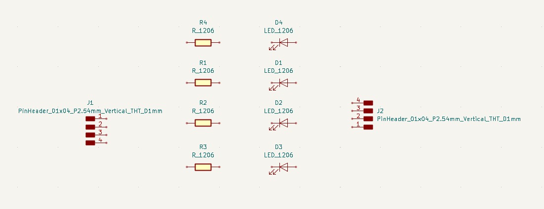
3. Selecting Components
I selected the electronic components needed for the project: three LEDs (red, yellow, green) and a 330Ω resistor for each LED to limit current. These components were chosen to ensure safe operation with the 5V supply of the board.
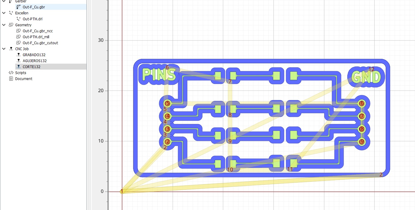
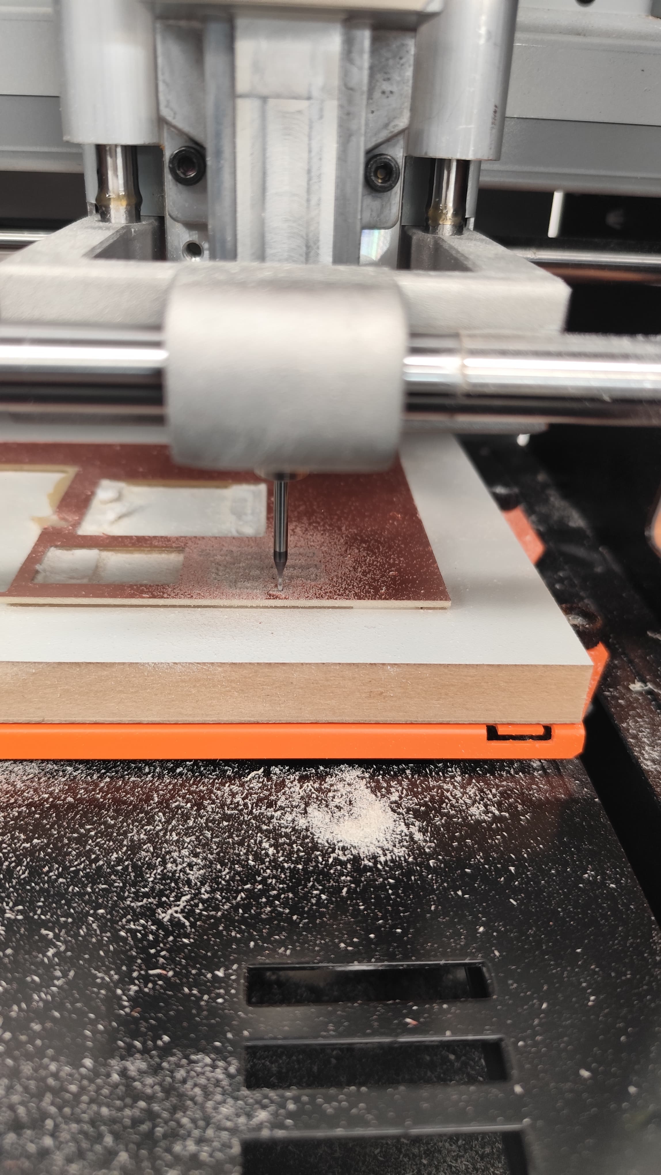
4. PCB Fabrication
I updated the PCB design from Week 8 to include headers for the LEDs and resistors. After exporting the Gerber files, I configured the toolpaths in FlatCAM and used the SRM-20 milling machine to fabricate the board.
5. Soldering Components
I soldered the ATtiny412, resistors, LEDs, and connectors onto the PCB. Each LED was connected to a digital pin (e.g., pins 2, 3, and 4) through its respective resistor, ensuring proper current flow and functionality.
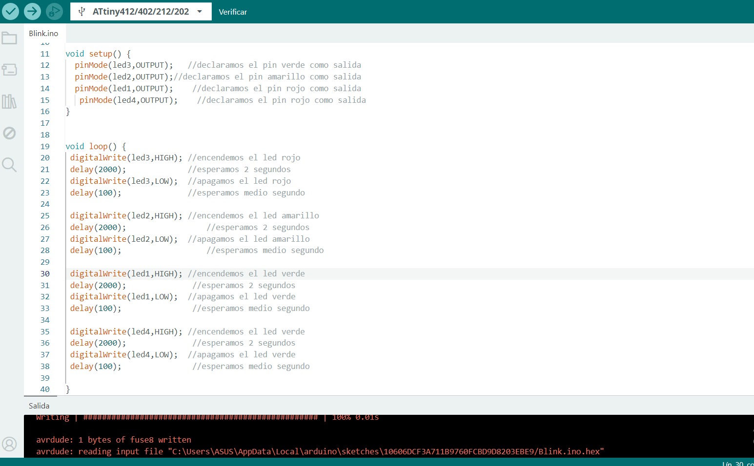
6. Programming the Traffic Light Sequence
I wrote a program in the Arduino IDE to control the LEDs in a traffic light sequence: green on for 5 seconds, yellow on for 2 seconds, and red on for 5 seconds. Below is the code I used:
#define RED_PIN 2
#define YELLOW_PIN 3
#define GREEN_PIN 4

void setup() {
    pinMode(RED_PIN, OUTPUT);
    pinMode(YELLOW_PIN, OUTPUT);
    pinMode(GREEN_PIN, OUTPUT);
}

void loop() {
    digitalWrite(GREEN_PIN, HIGH);   // Green ON
    digitalWrite(YELLOW_PIN, LOW);
    digitalWrite(RED_PIN, LOW);
    delay(5000);                     // Wait 5 seconds

    digitalWrite(GREEN_PIN, LOW);
    digitalWrite(YELLOW_PIN, HIGH);  // Yellow ON
    digitalWrite(RED_PIN, LOW);
    delay(2000);                     // Wait 2 seconds

    digitalWrite(GREEN_PIN, LOW);
    digitalWrite(YELLOW_PIN, LOW);
    digitalWrite(RED_PIN, HIGH);     // Red ON
    delay(5000);                     // Wait 5 seconds
}
The code was uploaded to the ATtiny412 using the Arduino Nano programmer.
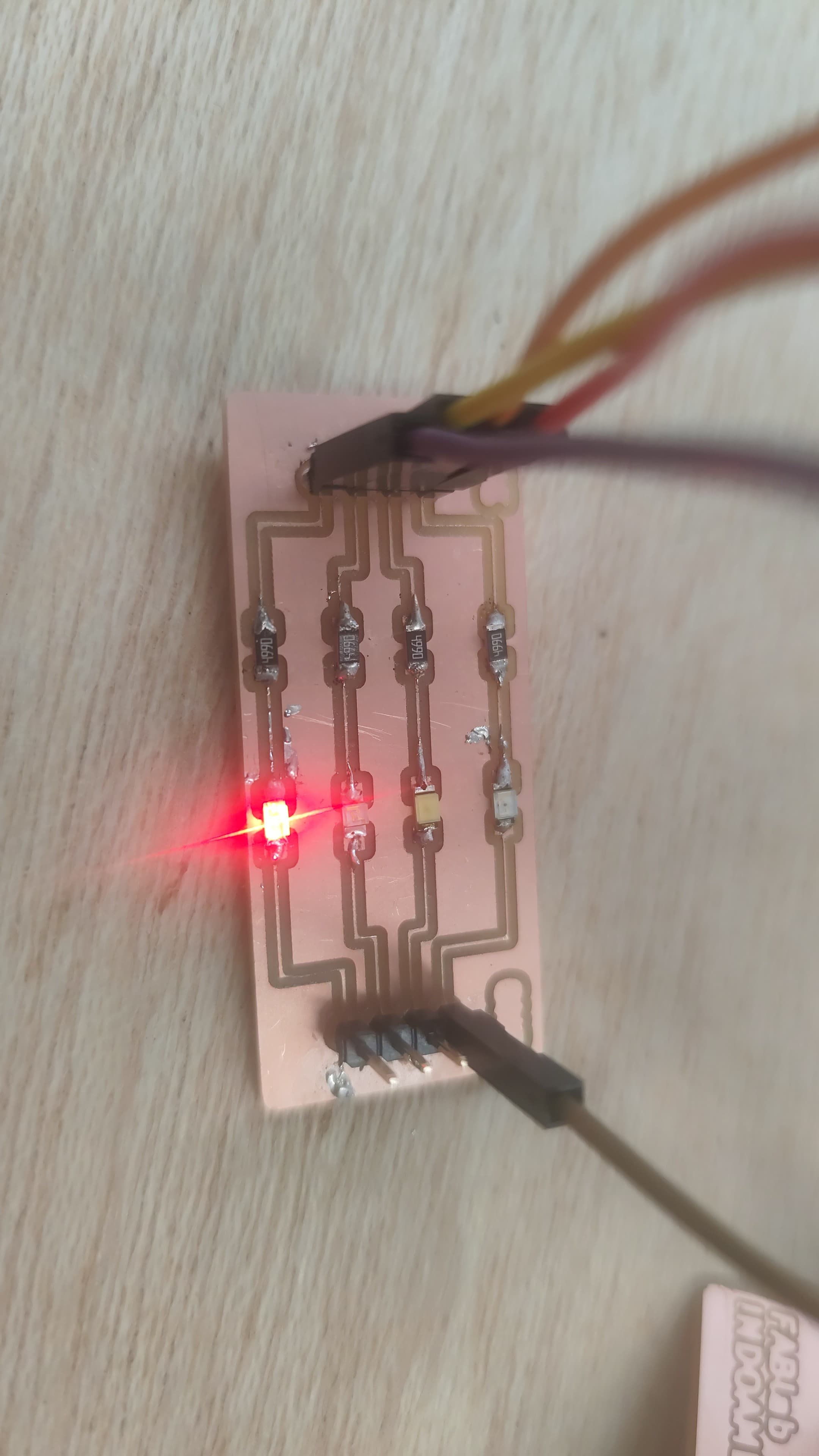
7. Testing the Operation
After uploading the program, I powered the board and tested the sequence. The LEDs turned on and off as expected, simulating a traffic light cycle. Below is a video demonstrating the operation:
Conclusion
This week, we learned that an output device is any hardware component that uses data and commands from its microcontroller to perform a specific task. This generates the results of data processing performed by an information processing system (such as a microcontroller), which converts the electronically generated information into a human-understandable format. By designing and programming a traffic light simulation with LEDs, I gained practical experience in connecting output devices to a custom board, writing control code, and troubleshooting the setup. This project enhanced my understanding of digital outputs and their applications in real-world scenarios.